Well I have embarked on a new project.
With the number of figures in my collection now approaching of 12,000 foot, 1,900 mounted and 450 guns and pieces of equipment, combined with my decision to slow down collecting and focus on playing games, I have decided to resolve an issue that has been bugging me for a while – a place to play games at home. I do not have a location for a permanent room so this requires me to sort out a table that can be setup and broken down in the garage.
The table is a simple enough thing. A commercially available table tennis table is all that is required – and it has a dual purpose of being able to play table tennis. I have found a good quantity one that will fold away into a corner of the garage without interfering with the true purpose of the place – garaging vehicles. This will be purchased in the near future, but it is not the table that is the project. I want to develop terrain tiles. I have always wanted to work with these but without a proper setup at home it was silly to consider them. So I have been thinking about them quite a bit over the last couple of months and I am at the point of starting work.
The size of the terrain boards was the was the first consideration. The ideal size for this would have been 800 mm square because that would have meant that two tiles would cover the short axis of the table (the table measures 2745 x 1525) with just a small, but manageable overhang. It did present an issue on the long axis, but the biggest restriction was storage in the garage. When stored the tiles could not extend more than 630mm from the garage wall without interfering with vehicle parking. So 600mm square would seem the perfect solution, except that it would provide too many joins – and the visible checkerboard look that joins create is the major negative with terrain tiles for me. A mix of rectangular and square tiles are the best solution in my mind to break the checkerboard look. To be practical the long axis of the rectangle must be double that of the short axis. Maybe 1200mm x 600mm (4 feet by 2 feet) could provide the solution.
The most important thing for me is that if I was going to go to the effort of making these things they had to be robust so thay they did not require constant maintenance and to me edge damage seemed to be the greatest risk. They needed hard edges to preserve the edge which has the added advantage that they will then fit together tightly, with as near an imperceptible a join as possible. My first thought was to construction a timber frame with a MDF base into which I could insert a piece of polystyrene sheeting. I had a couple of abortive attempts at constructing these, but I do not have a dedicated workshop nor the necessary tools for precision cutting. I even considered getting the frames professionally constructed until I saw the price!
Then I thought why not just use an MDF panel, afterall they can be purchased pre-cut at 1200mm x 600mm. Perfect. The initial concept was to use a piece of 25mm thick MDF and use router to cut out rivers, streams gullies, etc, but again the lack of a workshop space and the weight of a panel, put me off this idea. Instead I chose an option that may sound odd at first to use two boards, one 12mm and one 4.5mm thick. This means that for rivers and streams I can cut the shape easily with a jigsaw from the 12mm panel, which is quite deep enough and mount it on the thinner base. Alternatively I can put cut some cut cavities in the thinner sheet and put that sheet in top to reflect shallow depressions.
Then I sat down to figure out how many boards I needed to make. A quick calculation came to a minimum of seven rectangular boards and one 600mm x 600mm board would cover the table and give me a table 1800mm x 3000mm (6 feet by 10 feet). To that end I will create a mix of square and rectangular boards and many of the square ones can be specialist boards. But that brought about another problem – the overhang on each of the long edges would be 137mm and 127mm on the short edges. While those aren’t particularly big overhangs, if someone leans on the edge suddenly the troops are going to be catapulted across the garage. Again there is a simple solution. I chose to make four extension pieces that can be clamped onto the table with quick release wood working clamps. This extension doesn’t have to have any real strength, just enough to stop the catapult effect. Furthermore, by putting an edge on the extensions the terrain tiles can be locked in place to prevent movement.
Planning the Boards
I want to be able to game in both arid and temperate climates and that means creating two distinctly different sets: one with a green, or grassy finish and on with a brown or more arid finish. I figured I needed a greater variety in the grass than the arid finish. This set the overall number of boards. And this was set at ten 1200x600 and seven 600x600 green finish, seven 1200x600 and seven 600x600 arid finish in this configuration (this list may alter as the project progresses):

I looked at a number of options for surface cover, all of which had potential drawbacks:
- A textured surface using paint with sand added to it - the surface can chip or wear off and look tatty pretty quickly. I remember from my time at Peter Gilder’s Wargames Holiday Centre back in the mid-1980s that his tiles were made of particle board and painted plaster and in places the white of the plaster was showing through.
- A flocked surface using electro static flock and a flocking gun - will require me obtaining a flocking gun, flock and is potentially very messy
- A felt or similar fabric covering – the covering could peel away from the edges.
I quickly eliminated the flocked surface. I ran a couple of tests with the paint and sand style and while I liked the effect for the desert terrain I wasn’t as keen for greener terrain, although it worked really well for roads and areas of rough earth. The felt covering, with some sprayed tones of bright green and yellow, was the most pleasing to me.
With all this planning done I decided to build three board as a proof of concept. I chose to make a river/stream board and two plain with roads
The Proof of Concept
Board Number 1 – River section with a road crossing it at a ford and the road exiting on three edges
I decided to set the entry/exit points for rivers to be centred on the 300mm mark from any edge. Rivers require a standard size at the entry/exit point. Similarly the bank at the entry/exit point had to be at a consistent angle and I set that angle at 45 degrees, but after entry that angle could vary between 30 degrees and vertical. I wanted a bed width of around 100mm and a rim to rim measurement of 120mm. Another negative with terrain boards for me is the angular look of rivers. One way around this is to have the rivers entering at a 45 degree angle instead of square on, but I quickly dismissed this idea because too many boards were required to get reasonable combinations and setting up the cut to with consistency was beyond my minimalist workshop.
I wanted roads to enter at 120mm from the edge or either side of the long axis centre line on the 600mm edges. They will have a width at entry of 50mm.
My first task was to cut the river “cavity”. I set the jigsaw to cut at 45 degrees and cut the entry/exit points. Then I cut the rest of the cavity at 90 degrees, before going back with the saw set at 45 to give some variety. I also cut the cavity with curves that provided a variance of up to 100mm off the centre line. This was because with the thinner board underneath the thicker board a straight line through the centre would have increased the potential for the thinner board to warp.
With cavity cut the two sides of the river were glued to the base with PVA glue then clamped and the glue left to set.
When the glue was set I marked out the roads and began cutting the felt to fit the layout with an over hand of about 20mm from all the edges. This took quite a bit of fiddling around to get the most economic cut, and once done the pieces were glued down with PVA, taking care not to place glue on the road space. Then with a new craft blade I cut out the roads. The glued felt was then left to dry while I worked on the other two boards. Once the felt glue was dry I went back along the edges of the felt along the road edges with a bead of PVA to ensure that the edges were stuck down firmly.
The road surface was applied next. This was simple application of relatively coarse sand over a coat of PVA. The board was now left overnight for the glue to set hard.
It was too windy the next day to spray the felt so instead I focussed on creating the banks of the river. To eliminate the hard shape of the jigsaw cut I applied a commercial filler at a variety of angles then let it dry, which wasn’t a long time in the summer heat. I then applied toilet paper – yes toilet paper – fixed with generous amounts of PVA to the bank surface. This is a technique I have used for years and when the paper and glue mix the paper clumps and wrinkles that when painted creates a nice broken earth effect. I left the glue to set overnight while I glued the felt to the other trial boards. I also added a few pieces of pine bark on the outer bends of the river which will be painted as rock outcrops.
The next day, with much less wind, I sprayed the felt on all three boards. At first I applied a bright green, almost lime green, as irregularly as possible then before that had dried applied bright yellow. In both cases it was important to spray from no less a distance than 450mm otherwise the coverage is too light and no less than 300mm so that the appearance is not blotchy. It didn’t matter if the overspray went on the road or river areas because they are going to be completely repainted anyway.
Unsprayed
Part sprayed
Completely sprayed
The sprayed boards were then left to dry in a warm spot and when dry were stored while we went on our New Year’s trip to Fiji.
The next step was to give the roads and river banks a base coat of Burnt Sienna.
Once that had dried it was dry brushed with yellow ochre. This image shows a small area that has been dry brushed to illustrate how the texture of “toilet paper banks” begins to show up.
Then a dry brushing with a mix of yellow ochre and white. Finally a dry brushing of pure white for highlights. Again a small area is shown and you can see how the depth of colours brings up the texture.
A few green highlights are added to the river banks
The rock outcrops were first painted black then dry brushed several coats of gray, lightening the tone to almost white with each application.
The whole riverbed was then painted with Burnt Umber
Finally the base river colours are applied. For this I paint a dark blue down the center. Then before the blue dried I scumbled a bright green either side of the blue, allowing the colours to blend. The end result is a blend from bank to centre of brown to green to blue then back to green and brown to the other bank. When the water effect is applied this will give an appearance of depth.

The material I used for the water effect is an artists heavy gloss gel that I have used in a number of projects (such as the
Mill from 2016 and the
flatboats from last year). This stuff goes on white but dries clear. Because of its high viscosity it holds it shape so once it is applied across the surface it can be contoured to replicate turbulence. Reversing the old saying that sill waters run deep, I made the assumption that where the banks are steep the water is going to be deepest so I made this part the least turbulent. I don’t want this to be fast running water, but since water is rarely completely still I have just swirled it around so that when it dries it will just have a broken surface. Around the ford I have tried to make the water a little more still.
Above and below, the gel partly applied
Below, a detail image of the freshly applied turbulence
Below the turbulence partly dried
Below when the turbulence is fully dry.
But the finish lacked depth, so I applied a second coat and I am pleased with the result as seen below.
Board Numbers 2 and 3 - Plain with roads (one with a small field).
These were made using the same techniques as the river board.
With field...
Without
Part sprayed,...
Fully sprayed
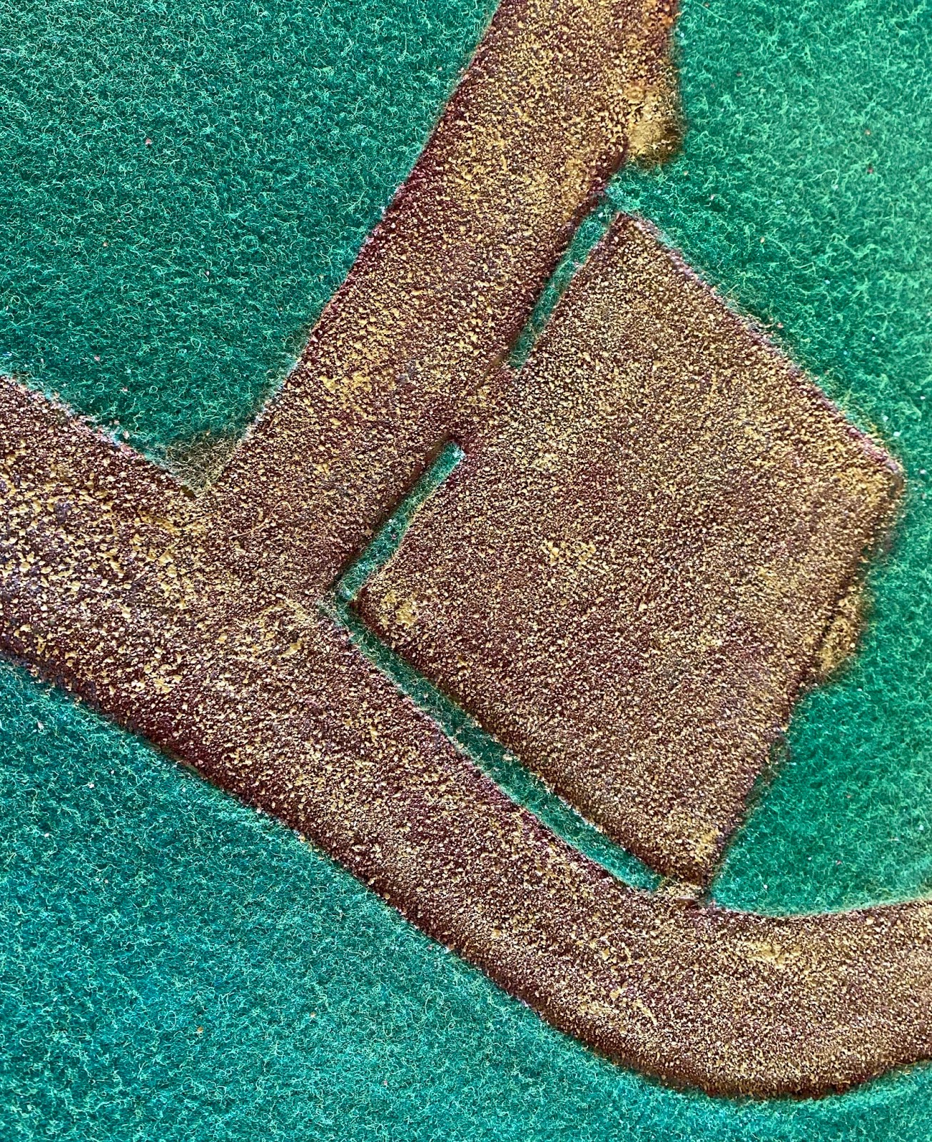
Roads with burnt umber...
...with yellow ochre...part and full...
And finished (again part and fully applied). A few thin strips of felt have been added to the road areas to represent where grass has grown in the centre of the road and on the road edge of the field.
So how did the proof of concept work out? Well there are the three boards in a few configurations.
Yes the line between each board is still visible, but with a bit more spray work this will blend a little better and when the other terrain items are placed (very roughly done here on the garage floor), many of those lines can be covered up.
Will the project go further? It certainly will, but not just yet. I am making one more board, with a hill as an extension to the proof of concept, but to make more beyond that I am going to have to organise the storage in the garage better that is a big job, involving some relocation of some of the garage contents to an outside shed that is not scheduled for construction until the middle of the year.


 Entrances to the area exist at the centre point of all four edges so that the piece can be rotated for variety.